 This is the second foilnose design. The motivation for this design is the experiment further with what appears to be a promising avenue of investigation: improving the L/D ratio by stiffing the leading edge.
The misfeature which I most want to eliminate from the first foilnose design is the deep creases parallel to the trailing edge of the canopy terminating at the bridle connection points. These creases are not the nice 'wows' seen on the wing leading edge of a typical NPW, but creases in the canopy perpendicular to the airflow when flown at low angles of attack. The bridling of the first foilnose allows for tuning to any AOA, but I believe it is the drag induced by these creases which limits the achievable minimum AOA.
Why do I want to achieve low AOA? The single greatest impact on a kites lift to drag ratio is its flying AOA. Peter Lynn's
Kite Design myth #1 describes this.
The foilnose designs look, well, weird with their non-textbook foil sections, but 'red thread' is that the design is being tuned for the most important aspect first: AOA. Even calling the inflated bumps on foilnose2 a foil is to stretch the definition! :-)
But, they serve the primary purpose of any inflated foil used on a kite: to prevent the nose from collapsing at low angles of attack. If this were not true, single skin kites would rule the skies, having left behind the slow reaction penalty of accelerating an enclosed volume of air, the weight penalty of three times the material, and the cost penalty of complex construction. In spite of all these drawbacks to inflated foils, they still dominate because their noses are less prone to collapse, allowing them to be flown at lower AOAs (giving higher L/D).
After the planform AOA is optimized, then a 'real foil' can be used instead of the inflated bumps. Design iteration is all about iteration. Dragging the overhead of a 'real foil' along each step of the way would slow the process. With family and work demands, low kite design iteration overhead is very appealing to me!
That was a little detour into kite design apologetics. Let's get back on track.
To eliminate the canopy creases, we first must understand the cause of the crease. There is a complex interplay of forces, but I think they can be summarized as: The skin creases along the shortest path between the bridle and the skin area under tension. Here are some ways balance or distribute this tension so the crease can be eliminated:
- Adding skin to the area which is creasing. The canopy can be sliced, and shaped patches of skin sewn in to balance the distance to the forces. Disadvantages: complex.
- Removing skin from the area which is creasing. This sounds opposite to the first strategy, but it is just a difference of where skin is added or removed. In this case a notch is sewn into the canopy from the leading edge along the line of the fold. This shortens the wing edge and lengthens the distance to the original stress point while shortening the distance to others.
- "Load curtain" type triangles between the bridle and where it previously attached to the edge of the canopy. The side where the triangles attach to the canopy is slightly convex, to emulate the "adding skin" strategy above.
- More bridle lines. At some point, there will be enough bridle lines for the canopy to 'wow' instead of crease at the bridle to canopy connection point.
- Creating inflated foil sections adjacent to the bridle connection points. Note that in the first foil nose, the bridle adjacent to the foil section did not create creases. The creases in the next two bridle points were stopped by the foil section they ran into. It appears there is enough 'stiffening' force in an inflated cell to counteract the creasing force of the bridle line spacing used in the first foilnose. So, instead of only having an inflated section on the nose, this inflated foil section would continue down the leading edge of the wing.
- Adjusting the shape of the skin so that only leading edge corner and trailing edge corner bridling is needed. Note that in the first foil nose, creases are only generated by the first and last bridle line when the forces on them are high.
For this design iteration, I chose the last strategy. To be honest, I could have tried something simpler from the list above, but I wanted to use my skin generation program described in the Parametric Kite Design article. Having said that, the last strategy does indicate or perhaps require a higher aspect ratio to implement. A higher aspect ratio also helps improve L/D.
Kite specs:
- Flat aspect ratio: 5.4 (using the w^2/a formula)
- Area: 3.3 m^2
- Tip to Tip: 4.23 m
- Center chord: 1.05 m
Yes, the color of this kite is again orange. I seem to have endless yards of this orange material. I don't think I will buy in bulk again. Everything looks blue after even a short sewing session with fluorescent orange ripstop.
The first foilnose had cross ventilation channels between the cells which would allow one cell to inflate a second cell, even if the second cell was not aligned with a stagnation point. Using the simpler cell construction technique, there was no cross ventilation of cells in foilnose2. This is bad from a synergistic standpoint, but good from the design feedback perspective in getting an accurate view of stagnation point effects along the leading edge of the kite.
A kite design commonly specifies the chord AOA at various parts of the kite, together with the PAP, profile alignment point along the span. This design uses a metric of the ratio between the length of the leading edge and the trailing edge to achieve the same purpose. I guessed at this value and came up slightly high, leading to a 'stally' kite. This can be fixed, and will be described during the analysis of the flight pictures.
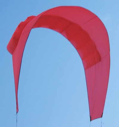
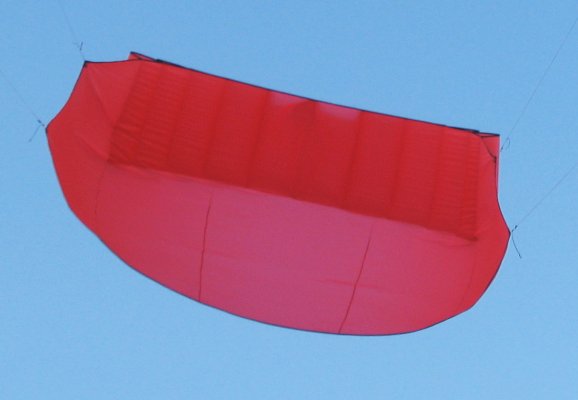
View from Back
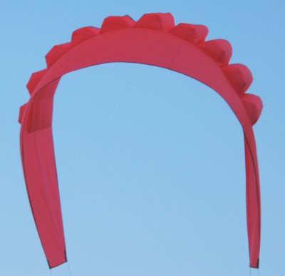
From the back view, we see a few things:
- There is no tip spar. However, there is no canopy deformation from using only two bridle points. Hurray!
- The mid canopy AOA is too positive, and the tip AOA is even negative!
- The 'bumps' on the side of the canopy seem to fill well, but the top ones lack inflation. This is closely related to the differences in AOA across the sail.
- Large sections of the wing tips seem to be doing no productive work, and drop straight down.
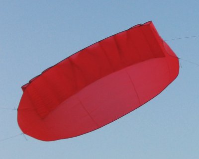
View from Side
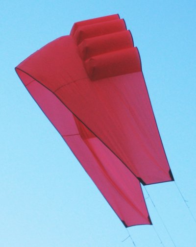
From the side view, we see a couple of things:
- No apparent bananna effect on the canopy from the cells, consistent with the first model.
- Removing tension from a rear line causes a wrinkle to appear from the front line to the rear of the first cell.
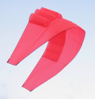
View from Under Kite
The bottom view shows even more clearly the negative AOA of the wingtips. Also seen here through the bottom canopy is the shadow of unfilled center cells.
Analysis
This design is stalling mid canopy, at the correct AOA at the shoulders, and flying a negative AOA at the wingtips. Wingtips with less AOA than the rest of the surface is called "tip wash-out". This trait is desirable for boat sails and sparred stunt kites. However, paragliders actually have tip "wash-in", where the tip has greater AOA than the rest of the sail.Overall, this design was created with too high a built-in AOA. Flying only on the font lines allowed a greater window, but had the effect of creating creases in the canopy due to too slack rear lines. Tightening the rears created a smooth canopy. In no case did the kite fly higher than 50°.
Improvements for This Model
Shorten the leading edge by making notches in the center most 4 cells. This will reduce the overall AOA of of the kite, especially in the center where it needs it most.With some extra fabric, I can make additional smaller bumps, making the 'foil' extend further down the wingtips.
Improvements for a New Model
The cells are actually longer than needed. I was too conservative in this design. A new design would use shorter cells.In this design, the cells start looking more and more monstrous moving closer to the tips. A new design would modulate the cell size to have smaller diameters towards the tips.
Closing
The great thing about designing single skin kites is that there is no 'cheating'. The skin impartially shows the forces acting on the kite by wrinkles and canopy shape. An inflated foil kite has the force of inflated cells to counteract minor imperfections in design. Perhaps the ultimate way to create a foil kite is first to create a smooth single skin kite and then base the foil version on the skin shape of the single skin version?This design turns out to look a lot like Peter Lynn's Arc design. No offense intended to Peter! This 'rough draft' is unattractive, and all Peter's Arc designs are polished and aesthetically pleasing. I'm just referring to general shape. Two differences: Arcs are fully inflated foils with spars at the tip. This design is sparless and uses 'two skins' only at the leading edge.
Related pages:
Everett Parawing
NPWC Foil Nose
FoilNose 3
Kite Design Parameters