 This is the third L/D improvement investigation
using chambers to stiffen a kite's leading edge. The idea comes from the
Everett Parawing modification to NASA Parawings.
This is the third L/D improvement investigation
using chambers to stiffen a kite's leading edge. The idea comes from the
Everett Parawing modification to NASA Parawings.
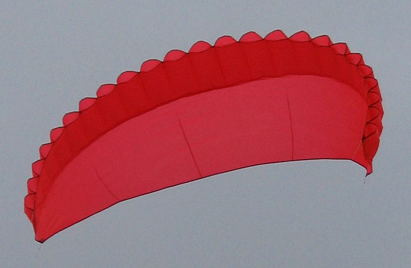
24 ram air inflated chambers run the entire length of the leading edge. Chambers are longer in the middle of the wing and shorter toward the tips. Each chamber has the same width.
This kite uses the same bottom skin, so it has the specifications as Foil Nose 2:
- Flat aspect ratio: 5.4 (using the w^2/a formula)
- Area: 3.3 m^2
- Tip to Tip: 4.23 m
- Center chord: 1.05 m
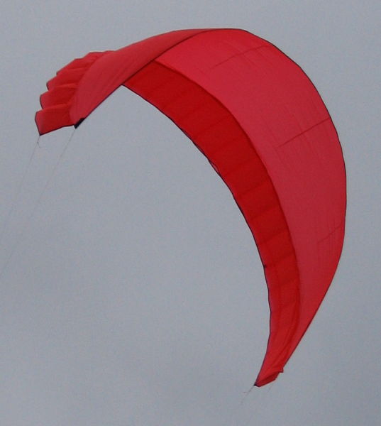
A view from the left rear of the kite is on the right side of this page. There are no bridles. Flying lines are run directly to the front and rear pigtails. There are no spars in this design, only shaped fabric and simple (no ribs) ram air inflated chambers.
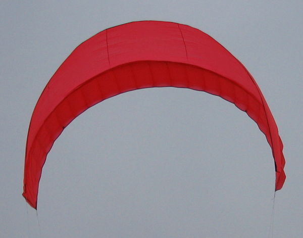
From the rear view below, we see a nice progressive curve of both the leading and trailing edge, indicating that all sections of the canopy are providing lift. This is in nice contrast to Foil Nose 2 where the tips were just for show.
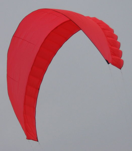
The right rear view of the kite shows the outside of the right tip. Here we see that the chambers are evenly inflated up the side of the kite.
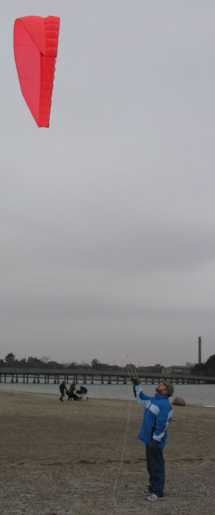
The first flight was on a bar. The test flying lines are about 4 meters long. Front lines end in the middle of the bar; rear lines end at the tips of the bar. Wind speed is a consistent 4.5 meters/second. The L/D is about 3.5 by line angle measure.
Points of interest:
- The force line (following the kite lines) intersects the canopy quite far back. Notice how the kite looks a little "tilted forward" when seen flying from the side. This tells me that the majority of the lift from the canopy is in the rearmost section. This is not necessarily a problem, in fact it's nice to know that the rear half of the canopy is actually providing some lift instead of just along for the ride.
- The center leading edge never collapsed. I need to play with the middle floating tensioning line to see how far I can push this and what the effects will be.
- The tips never folded in, but did stall-collapse when a rear line was pulled hard for a turn.
- Flying this particular implementation on a bar is not optimal. Trying to measure the side-to-side angle triggered this stall-collapse problem. Use handles.
Below we see a front view of the kite. Each cell is well inflated. We also see that some of the cells not only open "upwards" but also open slightly "downwards". This should come as a surprise as the force of the flying lines is normally transferred through the skin of the kite, keeping it quite taut. There is a secret here, I have saved the best part of the description for last.
This kite has an additional line in between the fabric layers, running the entire length of the leading edge. This line is "floating" inside the chambers, taking the load from the leading edge of the kite.
Floating Tension Line
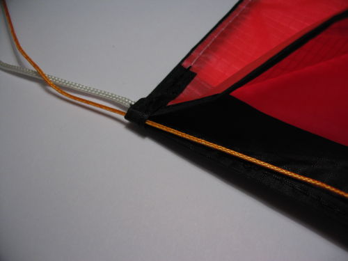
The "secret sauce" for this kite is the floating tension line in the leading edge of the airfoil section.The leading edge tension line exits the kite at the leading edge tip of the kite. Both the pigtail connected to the canopy and the free floating tension line ends with a knot (which is not shown in the picture). The forward flying lines lark head to both these knots when attaching to the kite. The leading edge tension line is made shorter by untying the knot and moving it to a position closer to the kite. A shorter line will allow the tube openings on the wing sides to be larger and shorten the length of the leading edge in this section.
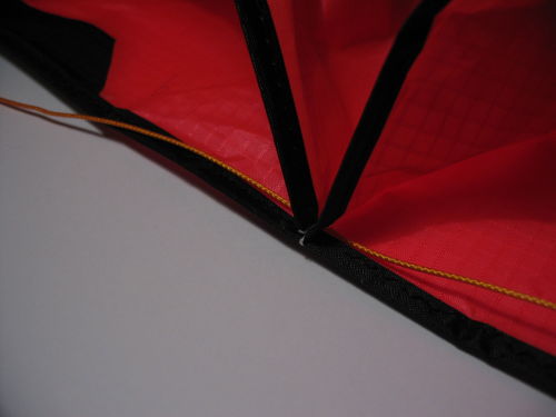
The picture below shows how the floating tension line travels between the canopy and the airfoil section. Line is threaded through the layers of fabric just behind the binding. I use a small knitting needle to open the stitching up a little so the line can be pushed through. Sewing machines and knitting needles: this is not sounding very macho, but these are the right tools for the job. If you use a 6mm stitch length, there should be plenty of room here.
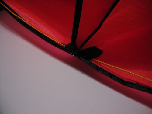
Each wingtip has 6 tube sections. The center has 12 tube sections. The center and tip sections are made independently adjustable by fixing the line between the center and tip section. This is done with a small section of fabric sewn to the tensioning line as shown in the below picture. The small section of fabric is sewn down on each wing side 6 tubes from the tip.
Go back through the flying pictures and notice the slightly darker dots on the leading edge of the kite one quarter the way up from each tip. These are the the small fabric squares shown here which fix the line to the canopy at that point.
There is one tensioning line for the right side and one for the left side of the kite. Lines are threaded between the layers of fabric along the leading edge. The amount the lines are tied together where they meet in the middle controls the contraction of the middle part of the leading edge and how much the tubes open in that section. Moving the tension line wingtip knot controls the same for the outer sections. The amount of wingtip knot movement should be uniform on each side.
This floating tension line has several benefits:
- Canopy design need not have a narrow window between stalling and luffing. Start "stally" and tension the floating sections until correct AOA is achieved.
- Independent tuning of the tips and center section. Each can be tuned to their own optimal AOA setting.
- Tensioning the line pulls the straight leading edge into a more stable concave shape.
For This Model
More testing and tweaking can be done without further touching the sewing machine:- How will wind speed affect L/D. I am happy with 3.5 in low wind - will more wind make the kite more rigid and push this higher?
- Handles are needed to test the side-to-side angle. The bar only allowed pulling in one rear while letting out the other. Handles provide more control input; especially important in this kite will be to shorten/lengthen both lines on a side at one time. Will the side-to-side angle match the vertical angle?
- Experiment with different amounts of floating line tensioning in both the center and wing sections. I just went with the eyeball setting from home with the first test flight, so this might open up some possibilities.
For a New Model
Some things will require sewing:- During flight, there a "wiggle" in the fabric between the rear pigtail and the inflated chamber closest to the front pigtail. This is especially visible in the front view picture. The "wiggle" could be solved by a spar along the tip edge. I wish to avoid spars, so instead I will try making the tip chamber extend all the way to the tip's trailing edge. It may be that this "wiggle" can be straightned by ram air pressure alone.
- At apogee the kite shows a spanwise wrinkle where the chambers terminate. Attempting to "fly higher" results in fabric folding under the cells reducing the chord of the kite. I can't quite figure out if this is an amazing new depower mechanism or a defect which could be fixed to provide higher L/D. Running a couple of center panel chambers most or all the way to the trailing edge would "fix" this.
Good news: I am out of orange fabric! Better color schemes are on the way. Stay tuned.
Learned So Far
Looking back on the foilnose series, I find:- Some thickness in the leading edge creates a lot more lift than a flat leading edge. There is a huge shape difference between foilnose 2 and this model.
- Single skin kites are not rigid. But even at aspect ratio 5.4 this kite is quite flyable and not prone to bow-ties unless I really mess up.
- Experiments using inflated chambers instead of "real" airfoils works fine. There are still plenty of parameters to tune before getting hard-core with foil sections.
- Internal tensioning lines can cover for imperfect canopy design and can tune a working design for different behaviors.
Related pages:
Foil Nose 2
Everett Parawing
NPWC Foil Nose
Kite Design Parameters