This article describes how to use Python Rhino Automation for Parametric Kite Design.
Terminology
Python is a high level programming language with clear syntax and powerful built in data types. I have been a C++ programmer for a number of years, but Python is my first choice for quick development and concise code.Rhino is a three dimensional CAD program which supports NURBS and surface unrolling. NURBS, Non-Uniform Rational B-Splines, are a standard mathematical model for describing curves. Surface unrolling is the ability to create a flat shape from a three dimensional surface.
Parametric automation is the ability to create an object based on key values. When the key values are updated, the object under automation reflects those changes.
Thus, "Python Rhino Automation for Parametric Kite Design" translates to creating a Python program which scripts a Rhino CAD model of a kite. This model can be updated by changing key features of a kite. There is no need to create the model from scratch by hand when an element of the kite design changes.
Motivation
A program such as foilmaker (stable link needed) or surfplan are the mainstream kite design programs. These are excellent in their domain, but like any program, are bound by the standard trade off of features vs. ease of use. If you have never designed a kite before, these programs are the place to start. They are effectively a system for parametric kite design where the set of parameters and the method for meeting them is determined by the program.When a kite designer is not satisfied with the available parameters or how the parameters are solved, two paths are left: using a CAD program or implementing a new kite design program to cater for their special needs. Examples:
- Hangtime kite design software takes the "new kite design program" approach to achieve long panels with smooth lines for inflatable kites.
- Tom White has programs which specialize in NPW single skin kites.
- Olivier gives an excellent walkthrough of the complete customization of all parameters of kite design available when using a CAD program.
The "new kite design program" solution removes the limitations of the mainstream kite design program which bothered the author of the new program, but also introduce a new fixed set of parameters and solutions to those parameters. Using a CAD program gives ultimate flexibility, but if a design decision changes, the model must be rebuilt by hand to incorporate the new idea.
This article aims to achieve the best of both worlds: ultimate flexibility of a CAD program, combined with the ease of changing fundamental design parameters. Caveat et emptor: nothing is free! This requires some (relatively simple, depending on your ambition) programming. I don't take any credit here - I beleive it was Andy Wardley who pioneered parametric kite design using Perl. Check out his article to see the other area he pioneered.
Automating Rhino with Python
There are three approaches or levels to automating Rhino:- Command Pasting: a simple set of Rhino commands are pasted into the command window.
- Command Languate Automation: a program is created to generate the commands which are pasted into the command window.
- COM Automation: Rhino is controlled at the component level.
Command Pasting
Rhino has a command window which can be used tell Rhino what to do.
Copy the following text and paste it into the command window, and some lines will show up in the Rhino viewport.
line 3,4 22.5,3
See also the code used on the NPWC v8 page. This level of Parametric Design is appropriate if the parameters being varied are quite simple, like the control points for drawing the wing panel on the v8 page.
Command Language Automation
This approach is a level of indirection from from Command Pasting where code is written to generate the commands, instead of editing the command code directly. To elaborate on this I will go through an example to create a kite skin based on the following parameters:- Tip width, how wide the tips of the kite should be.
- Tip start angle in degrees. This controls the aspect ratio of the kite.
- Number of notches to sew in fabric.
- How deep to sew the notches. This controls the LE/TE ratio.
- The total concavity of the trailing edge in degrees.
- Trailing edge length.
# python script to generate Rhino commands for SSTEA
# 2007-4-1, v1.0, Bill Ola Rasmussen, based on NPWK code
# 2007-4-6, v1.1, Bill Ola Rasmussen, vertical notch
from math import sin, cos, pi, radians
# parameters ------------------------------------------------------------------
tw = 3  # - tip width
sa = 45 # - start angle (degrees)
nc = 6  # - notch count
nd = 60 # - notch depth % (controls LE/TE ratio)
tc = 8  # - TE concavity (degrees)
tl = 50 # - TE length
# conversions -----------------------------------------------------------------
sa,ca,tc = radians(sa),radians(sa),radians(tc) # math operates with radians
nd = nd*.01         # convert percentage
tl = tl/float(nc+1) # convert TE length to TE segment length
tc = tc/float(nc*2) # convert TE concavity to half notch concavity
na = 2*ca/nc        # notch angle without tc (same as TE notch deflection)
# all notches are vertical, only calculate angles once
cpa = na/2+tc-pi/2  # control point angle of notch
lwa = (cpa-pi/2)/2  # left wall angle of notch
The second block sets up utility classes for calculations on lines, points, and splines. These classes represent their respective concepts, and allow themselves to be expressed as Rhino commands.
# classes ---------------------------------------------------------------------
class Point:
    '2D Point from x and y values.'
    def __init__(self, x, y):
        self.x,self.y = float(x),float(y)
    def __str__(self): # rhino script format
        return '_point '+self.pt()
    def pt(self):
        return '%f,%f'%(self.x,self.y)
    def to(self,a,m):
        'Make new line from point: angle a, length m.'
        return Line(Point(self.x,self.y),
                    Point(self.x+cos(a)*m, self.y+sin(a)*m))
    def toP(self,p):
        'Make new line to Point.'
        return Line(self,p)
class Line:
    'Line segment from two Points.'
    def __init__(self, p1, p2):
        self.p1,self.p2 = p1,p2
    def __str__(self): # rhino script format
        return '_line %s %s'%(self.p1.pt(),self.p2.pt())
    def mid(self):
        return Point((self.p1.x+self.p2.x)/2,(self.p1.y+self.p2.y)/2)
    def intersect(self, line):
        'Intersection of two lines. Intersects can occur outside of segment.'
        # see http://local.wasp.uwa.edu.au/~pbourke/geometry/lineline2d
        denom = (line.p2.y-line.p1.y)*(self.p2.x-self.p1.x)- \
                (line.p2.x-line.p1.x)*(self.p2.y-self.p1.y)
        #If the denominator is 0 then the two lines are parallel.
        if 0==denom: raise # todo: error handling
        ua = ((line.p2.x-line.p1.x)*(self.p1.y-line.p1.y)- \
              (line.p2.y-line.p1.y)*(self.p1.x-line.p1.x))/denom
        return Point(self.p1.x+ua*(self.p2.x-self.p1.x), \
               self.p1.y+ua*(self.p2.y-self.p1.y))
    def to(self,a,m):
        'Make new line followng this one: angle a, length m.'
        return self.p2.to(a,m)
    def toP(self,p):
        'Make new line followng this one: to Point.'
        return self.p2.toP(p)
    def toY(self,a,y):
        'Make new line followng this one: angle a, ends at location ?,y.'
        al = self.to(a,1)                # angle 'a' line
        hl = Line(Point(0,y),Point(1,y)) # horizontal line at y
        return Line(Point(self.p2.x,self.p2.y),al.intersect(hl))
class Spline:
    'Spline from three Points.'
    def __init__(self, p1, p2, p3):
        self.p1,self.p2,self.p3 = p1,p2,p3
    def __str__(self): # rhino script format
        return '_curve %s %s %s _enter'%(self.p1.pt(),self.p2.pt(),self.p3.pt())
The third block is where the heavy lifting happens. The code sets a starting location and draws lines for each trailing edge segment and splines for each notch. The key thing that happens here is that the center control point for the spline is defined so that each notch creates a concave juncture at the trailing edge (when the tc parameter is positive).
# start of main code ----------------------------------------------------------
print '_selall\n_delete' # clear previous drawing
start = Point(0,0)
te = start.to(ca,tl);                     print te # virtual trailing edge
tip = start.toP(Point(0,tw));             print tip
ete = tip.toP(te.p2);                     print ete # extended trailing edge
for i in range(nc):
    # notch splines
    depth = (1-nd)*te.p2.y
    lsw = te.toY(lwa,depth)             # left spline wall
    mnl = lsw.to(pi/2,1)                # mid notch line
    cpl = te.to(cpa,1)                  # control point line
    ccp = mnl.intersect(cpl);             print ccp # center control point
    print Spline(lsw.p1, ccp, lsw.p2)
    rsw = lsw.toY(-lwa,lsw.p1.y);       # right spline wall
    print Spline(rsw.p1, ccp, rsw.p2)
    # TE
    ca -= na
    te = rsw.to(ca,tl);                   print te
tip = te.to(pi/2,tw);                     print tip
ete = tip.toP(te.p1);                     print ete # extended trailing edge
print '_zoom extents'
print 'done, angle error: %f, y error: %f'%(ca+sa,te.p2.y)
When the above three blocks of code are joined together and run in the Python interpreter, the following output is produced:
_selall
_delete
_line 0.000000,0.000000 5.050763,5.050763
_line 0.000000,0.000000 0.000000,3.000000
_line 0.000000,3.000000 5.050763,5.050763
_point 5.267103,3.543256
_curve 5.050763,5.050763 5.267103,3.543256 5.267103,2.020305 _enter
_curve 5.267103,2.020305 5.267103,3.543256 5.483442,5.050763 _enter
_line 5.483442,5.050763 11.669338,8.622191
_point 12.038653,6.048716
_curve 11.669338,8.622191 12.038653,6.048716 12.038653,3.448877 _enter
_curve 12.038653,3.448877 12.038653,6.048716 12.407969,8.622191 _enter
_line 12.407969,8.622191 19.307439,10.470899
_point 19.755940,7.345638
_curve 19.307439,10.470899 19.755940,7.345638 19.755940,4.188360 _enter
_curve 19.755940,4.188360 19.755940,7.345638 20.204441,10.470899 _enter
_line 20.204441,10.470899 27.347298,10.470899
_point 27.795799,7.345638
_curve 27.347298,10.470899 27.795799,7.345638 27.795799,4.188360 _enter
_curve 27.795799,4.188360 27.795799,7.345638 28.244301,10.470899 _enter
_line 28.244301,10.470899 35.143771,8.622191
_point 35.513086,6.048716
_curve 35.143771,8.622191 35.513086,6.048716 35.513086,3.448877 _enter
_curve 35.513086,3.448877 35.513086,6.048716 35.882401,8.622191 _enter
_line 35.882401,8.622191 42.068297,5.050763
_point 42.284637,3.543256
_curve 42.068297,5.050763 42.284637,3.543256 42.284637,2.020305 _enter
_curve 42.284637,2.020305 42.284637,3.543256 42.500977,5.050763 _enter
_line 42.500977,5.050763 47.551740,0.000000
_line 47.551740,0.000000 47.551740,3.000000
_line 47.551740,3.000000 42.500977,5.050763
_zoom extents
Copying the above command language into the Rhino command window produces the lovely kite skin design below:
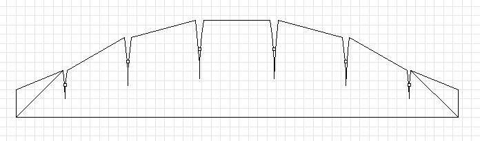
The key to this excercise is that we can create a totally new drawing - just change a parameter in the Python file, run the program again, then paste the output into Rhino to create another drawing. Various adjustments can be made, and we do not need to draw by hand from scratch when a requirement changes.
The purpose of this particular skunk works skin design will be kept secret for now. [Update: no longer a secret, see the FoilNose2 page.] However, some clues can be gleaned from my theory of sparless single skin kite design: the combination one necessary condition and one key value helps determine if the kite will fly. The necessary condition is that there are no unsupported (e.g. unbridled) convex sections on the (3D) outline of the kite. The one key value is the ratio between the length of the leading edge and trailing edge of the kite.
The code presented enforces the necessary condition via the tc parameter. Adding the ratio calculation and reporting is left as a excercise for the reader.
COM Automation
 When even more control over Rhino is desired, COM automation can be employed to interface to Rhino.
This opens up the possibility to manipulate objects after drawing them.
I will leave this for an entirely new article, as this one has already grown large
enough. Until then, you can click on the image to see a kite model created using Python via the Rhino COM interface.
When even more control over Rhino is desired, COM automation can be employed to interface to Rhino.
This opens up the possibility to manipulate objects after drawing them.
I will leave this for an entirely new article, as this one has already grown large
enough. Until then, you can click on the image to see a kite model created using Python via the Rhino COM interface.
Closing
Use an existing kite design program if it fits your needs. Programmed CAD automation can be used for design cases where existing programs are too limiting.Variations are possible. This article uses Python and Rhino, which means a Windows environment. My main computer now runs Ubuntu, so I would love to learn how to accomplish something similar with Blender.
Related pages:
Kite Design Parameters
FoilNose2