NASA TN D-5974 "Wind tunnel studies of effects of construction methods, design details, and canopy slots on the aerodynamic characteristics of small-scale all-flexible parawings" was published in October, 1970. It describes 12 variations on single keel parawings. On the NASA Parawing Reports page, the report file is 19700031435_1970031435.pdf.
This article describes the "revised line attachments" single keel parawing variation. Details are provided so that construction of this model as a kite or glider can be accomplished.
Layout
Figure 16 of the report shows the panel layout and line attachment points:
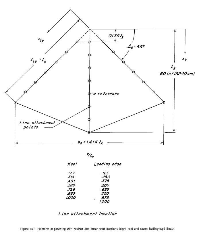
In the figures, lk denotes "keel length of theoretical wing-canopy flat planform, measured from theoretical apex to the trailing edge at the plane of symmetry". Let's go through all the symbols and text in figure 16 to make sure we are on the same page:
- "xle": the leading edge measurement starts from the tip of the virtual nose of the kite.
- "lle = lk": the length of the leading edge (including the cut off nose) is the same as the keel length.
- "0.125 lk": the nose is cut of by 1/8 the keel length.
- "Λ0 = 45°": the wing sweep angle is 45 degrees.
- "lk 60 in.": the keel length (including the cut off nose) is 60 inches. (this means the actual keel length of the tested model is 52.5 inches)
- "xk": the keel measurement starts from the tip of the virtual nose of the kite.
- "b0 = 1.414 lk": the tip to tip wingspan is 1.414 times as long as the keel.
- "x/lk": line attachment location measurements are in nondimensional units proportional to the length of the keel.
This particular single keel parawing design has two unique aspects:
- The spacing of the canopy attachment points is uniform along both the keel and the leading edge. In the "standard" single keel parawing described in many of the NASA reports, both keel and leading edge have non-uniform canopy attachment point spacing.
- There are only 22 canopy attachment points - 7 on each leading edge, and 8 on the keel. The "standard" single keel parawing uses 23 canopy attachment points - 6 on each leading edge and 11 on the keel.
Page 11 of the report talks about the revised attachment point strategy: "The line arrangement used on the basic wing was developed in free-glide tests of small hand-launched models and was retained because it appeared to work very well for wings having keel lengths up to 60 ft (18.288 m). Inasmuch as the shape of the inflated canopy is dependent upon the number, location, and lengths of the suspension lines, tests were made to determine effects of revised line attachments on the aerodynamic characteristics. Basic data for a model with eight keel lines and seven lines on each leading edge are presented in figure 17 and compared with results of the basic wing in figure 38. The comparison of data in figure 38 shows that the revised line attachments had very little effect on the maximum lift-drag ratio or the variation of lift-drag ratio with resultant-force coefficient."
So we see that this simplified bridling of a single keel parawing incurs no performance penalty.
Performance
Figure 38 performance data is shown here:
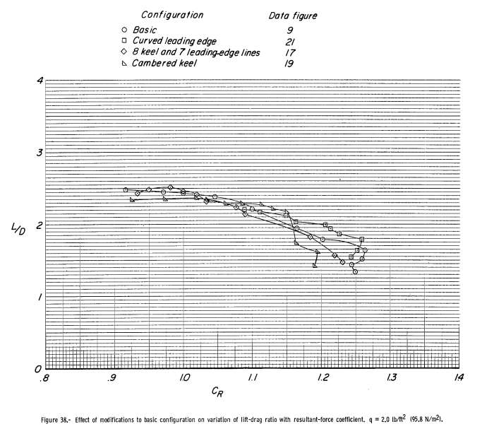
Figure 38, above, shows performance very similar to the "standard" single keel parawing - the L/D tops out around 2.5. In fact, at maximum L/D for each model, this model produces slightly more pull than the "standard" model.
Line Lengths
Below is the part of figure 17 which shows a graph of the line lengths for this model.
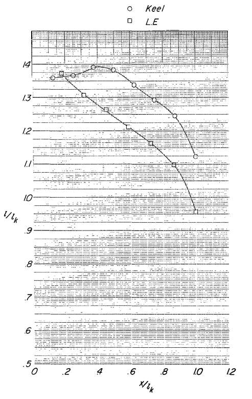
In the above figure, l/lk denotes "nondimensional length of suspension lines measured from wing attachment to top of clamping block" and x/lk denotes line attachment point along wing leading edge or keel. This graph does not show the profile shape of the parawing.
Confluence Points
One challenge in creating the NASA Parawing Profiles article (modelling the profile shape of the various NASA wings) involved confluence points. The last lines on the leading edge and keel were routed to a different confluence point than the rest of the lines. The definition of l/lk as "to top of clamping block" in this report seems to indicate a measurement to a single confluence point.However, page 8 of NASA TN D-5974 states: "The suspension lines for all of the models were held at the confluence point in a clamp as shown in figure 2. Dimensions pertinent to the location of the line attachments in figure 2 are given in table I for each data figure. The model could not be tested in the wind tunnel with the one-point suspension system normally used in free-glide flight tests because the model diverged in roll when tethered to a single point. In order to stabilize the model so that data could be obtained, the attachment points of the rear keel and tip lines were moved rearward, and the tip line attachments moved outward by means of the special rigging mount shown in figure 2."
The description is not clear: "the confluence point" is singular, indicating a single point. But "so that data could be obtained, the attachment points of the rear keel and tip lines were moved rearward" indicates that perhaps the line length data was recorded with a multiple confluence points.
On the one hand, the two graph curves connecting all points in figure 17 above is misleading if the confluence point for the last suspension lines is different from the rest of the suspension lines. On the other hand, it is not explicitly stated that a calculated or physical movement of the last suspension lines to a single confluence point was done after the suspension line lengths were adjusted for best flight.
My educated guess at this point is: the last suspension line lengths are based on a different confluence point than the rest of the suspension lines. A single line kite or glider rigged using these line lengths would not perform as well as expected, and may even stall.
Profile
Reading the line lengths from the graph in the previous section gives the following line length table. All lines lead to a single confluence point:
| Point | l/lk Wing | l/lk Keel |
|---|---|---|
| 1 | 1.373 | 1.359 |
| 2 | 1.306 | 1.366 |
| 3 | 1.264 | 1.391 |
| 4 | 1.212 | 1.382 |
| 5 | 1.162 | 1.334 |
| 6 | 1.098 | 1.293 |
| 7 | 0.956 (1.026) | 1.245 |
| 8 | NA | 1.123 (1.163) |
The numbers in parenthesis indicate a value corrected for measurements if taken from a testing harness where the last wing and keel lines have a different confluence point than the rest of the lines. NASA TN D-5936 (describing parawings 1-10) gives a line length adjustment for free flight: "By comparing the line lengths for model 5 in table II with those in figure 28, it is found that an increase in the aft-keel-line length of about 0.04 lk and an increase in tip-line length of about 0.07 lk was necessary to rig for free flight." This method was used to calculate the parenthetical numbers.
Running these line lengths through the process described in NASA Parawing Profiles gives the following profile pictures. The first picture is with unadjusted (not using the values in parenthesis). The second is adjusted as described above.
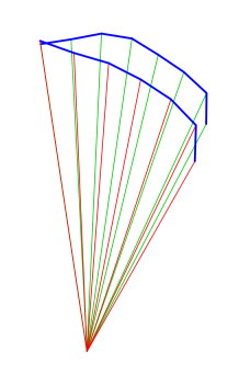
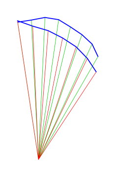
The second profile picture looks to be the most reasonable. We will use the adjusted values.
We now have enough information to create a plan for this "revised line attachments" style parawing. See the articles below for more.
Related articles:
NASA Single Keel Parawing - Plans and Construction (coming soon)
NASA Single Keel Parawing - Flight Pictures (coming soon)
Nasa Parawing Research
NASA Parawing Reports